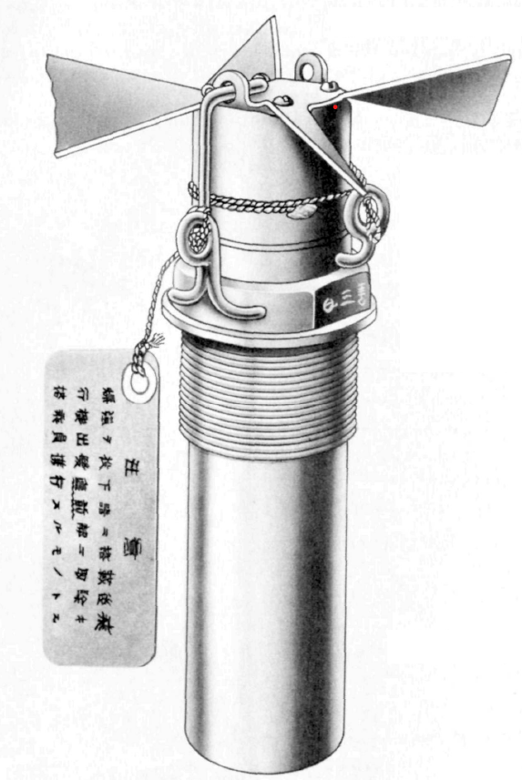
Description
Natural brass, maroon lacquered lower body. Steel vanes.
There are spanner wrench flats on side of body. No anti-withdrawal or locking device is used.
The fuze consists of three main parts: the body, the striker spindle, and the arming vane assembly. The striker spindle is located in the fuze body by means of a locating screw and a shear wire which prevent the spindle from rotating or moving forward until impact. The upper portion of the spindle is threaded while a steel firing pin is screwed into the lower end. The arming vane assembly consists of a nose cap, arming vanes, and arming sleeve. The arming sleeve internally threaded, screws onto the spindle and its length of travel is limited by a stop screw threaded into the top of the spindle. To this sleeve, the nose cap and arming vanes are attached by four short screws. The lower end of the fuze body is internally threaded to take the standard Japanese gaine or magazine.
A heavy wire eyelet is attached to the side of the fuze body and serves as a guide for the starting wire. The starting wire is soldered to the nose cap in two places and gives an initial turn to the arming assembly when the bomb is dropped. A safety fork fits into the upper portion of the fuze body, one prong of which extends up through eyelets of arming vane assembly to prevent premature vane rotation.
This fuze is similar to the A-3(a) with the following exceptions: (a) the maroon lacquered lower fuze body is 1 7/16 inches longer than that of the A-3(a); (b) the striker spindle of the new fuze is longer than that of the A-3(a) to match the elongated lower fuze body; (c) the vanes have a span of 4 3/4 inches as compared to the 3 1/2 inch vane span of the A-3(a).
This fuze has the same uses as the A-1(c).
Functioning
On release of bomb, the arming wire pulls the starting wire through the eyelet, breaking it loose at the soldered points and simultaneously imparting an initial rotation to the arming vane assembly. In seven revolutions, the arming sleeve rises up the striker spindle to lock against the stop screw and arm the fuze. On impact, the entire assembly (vanes, nose cap, sleeve and spindle) is driven inward, shearing the shear wire, and the firing pin pierces the primer.
Hazardous Components
Standard Navy gaine or magazine.
Physical Data
Length, overall - 7.13 in (181 mm)
Width, overall - 2.25 in (57 mm)
Vane span - 4.75 in (121 mm)
See Also
Nose, A-1(c), Type 2 Model 1 Mod 3
Nose, A-3(a), Type 97 Mk 2 Model 2
Source(s)
OP 1667, Japanese Explosive Ordnance, Volume 1 (1946)
TM-E9-1984, Enemy Bombs and Fuzes, Section VII, Japanese Fuzes (1942)
