Description
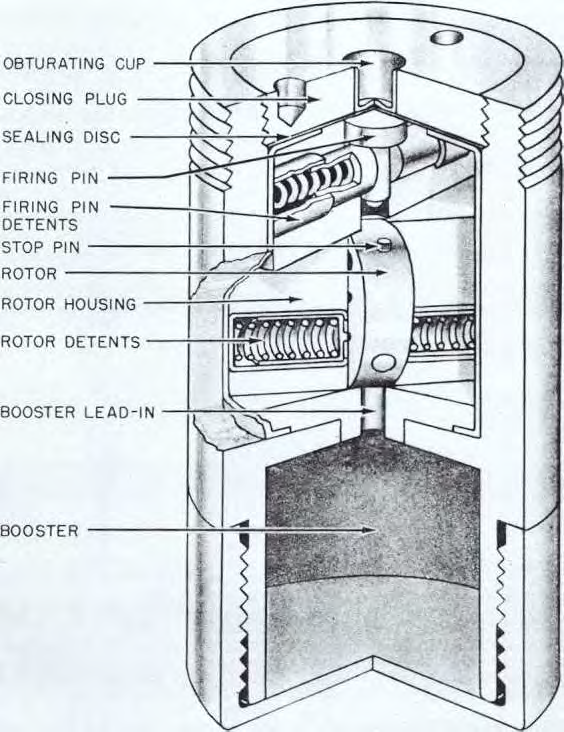
The fuze is composed of a one piece body, with a booster cap and plug closing the ends. The body assembly consists of the firing pin housing and rotor housing, both of which are contained in the sealing cup. In the middle of the closing plug is an obturating cup with a sealing disc between the plug and the firing pin housing. The firing pin housing contains a metal firing pin which is held in position by two firing pin detents. Contained within the rotor housing are a rotor and two rotor detents. The rotor, which contains two lead counterweights and the detonator, is assembled in the housing with the axis of the detonator at an angle of about 55 degrees from the axis of the fuze. The line of centers of the lead counterweights is at an angle of about 35 degrees from the axis. The rotor is held in the unarmed position by the two rotor detents, the tapered ends of which engage in holes in the side of the rotor.
This fuze is not designed to function by itself, but will function only by the gas pressure from a nose fuze.
Mods 0-6, representing different manufacturers, were originally assigned for use in 3 inch to 16 inch AA, AA Common, and HC projectiles. Later assignments restricted their use to 3 inch to 6 inch projectiles. Mods 0 to 6 were then withdrawn from service and replaced by Mods 8-13, later redesignated as the Auxiliary Detonating Fuze Mk 46. A special "green stripe" Auxiliary Detonating Fuze Mk 17 Mod 8 with weaker detent springs was assigned to be used in major caliber HC ammunition. This fuze was later redesignated the Auxiliary Detonating Fuze Mk 35.
Mods 8-13 of Auxiliary Detonating Fuze Mk 46 differ from Mods 0-6 as follows:
1. To insure positive rotation, two additional lead counterweights were added to the rotor and two holes drilled in the rotor opposite these weights.
2. Two stop pins were added to the rotor, and two holes were cut in the rotor housing to engage the stop pins to prevent further rotation of the rotor after the detonator had become aligned with the firing pin.
Mk 17 Mods 0-11 are considered obsolete.
Functioning
As the projectile is fired from the gun, centrifugal force moves the firing pin and rotor detents back against their springs. Then centrifugal force, acting upon the lead counterweights in the rotor, will cause the rotor to turn until the detonator assembly is in line with the booster lead in and firing pin. In this position, the rotor is dynamically balanced, centrifugal force holding the two lead counterweights at a maximum radius from the axis of rotation of the fuze. When the nose fuze functions, the gas pressure from it forces the obturating cup down, shearing the sealing disc adjacent to the firing pin and driving the firing pin down into the primer-detonator assembly which fires the booster lead in and the booster.
Hazardous Components
No information about hazardous components.
See Also
Source(s)
MIL-HDBK-146, Fuze Catalog (1982)
OP 1664, Volume 1 - US Explosive Ordnance (1947)
