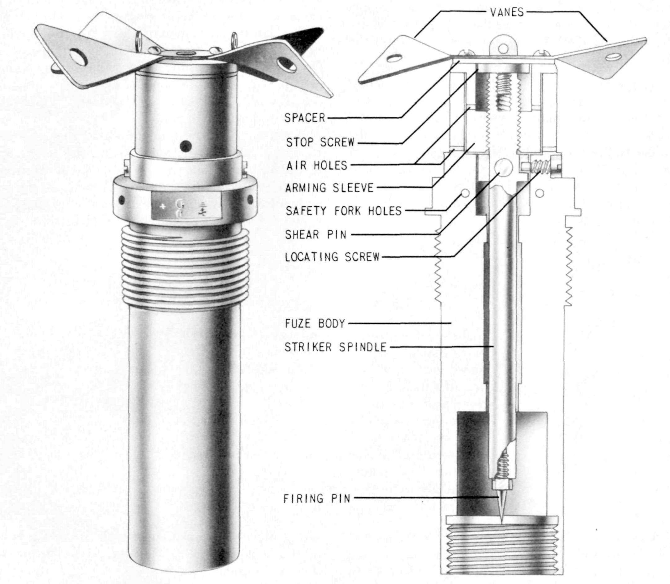
Description
The fuze consists of three main parts: the body, the striker spindle and the arming vane assembly.
The striker spindle is positioned in the one piece fuze body by a locating screw and steel shear pin 15/64 inch in diameter. The upper portion of the spindle is threaded externally and internally and a steel firing pin is screwed into the lower end.
The arming vane assembly consists of vanes, spacer disc, arming sleeve and stop screw. The internally threaded arming sleeve screws onto the striker spindle. A stop screw threaded into the upper end of the spindle prohibits the sleeve from screwing off the spindle. The arming vanes and spacer disc are attached to the sleeve by four short screws. There is a 1/4 inch hole in each vane 1/4 inch from its end.
A safety fork fits into the upper portion of the fuze body, one prong of which extends through the eyelets of the arming vane assembly thereby holding it stationary.
This fuze is similar to the A-3(d) with the following exceptions:
(a) the nose cap is replaced by a spacer disc;
(b) the shear wire is replaced by a shear pin;
(c) there is no flange on the fuze body above the threads;
(d) there is no starting wire or eyelet on the fuze body.
Functioning
When the Baka bomb is released from the plane, an arming wire is withdrawn from the holes in the arming vanes. The vanes rotate causing the arming sleeve to rise up on the striker spindle and lock against the stop screw. On impact with a solid object the arming vane assembly and striker spindle are driven inward shearing the steel shear pin and the firing pin pierces the primer.
Hazardous Components
Components of the explosive train are incorporated in the Navy gaine.
Physical Data
Length, overall - 7.13 in (181.1 mm)
Width, overall - 2.05 in (52.1 mm)
Vane span - 4.75 in (120.7 mm)
See Also
Nose, A-3(d), Type 97 Mk 2 Model 1
Tail, B-9(a)
Tail, B-10(a)
Source(s)
OP 1667, Japanese Explosive Ordnance, Volume 1 (1946)
TM-E9-1984, Enemy Bombs and Fuzes, Section VII, Japanese Fuzes (1942)
