Description
All brass except spring and firing pin.
Screwed into tail cone with spanner wrench fitting in holes.
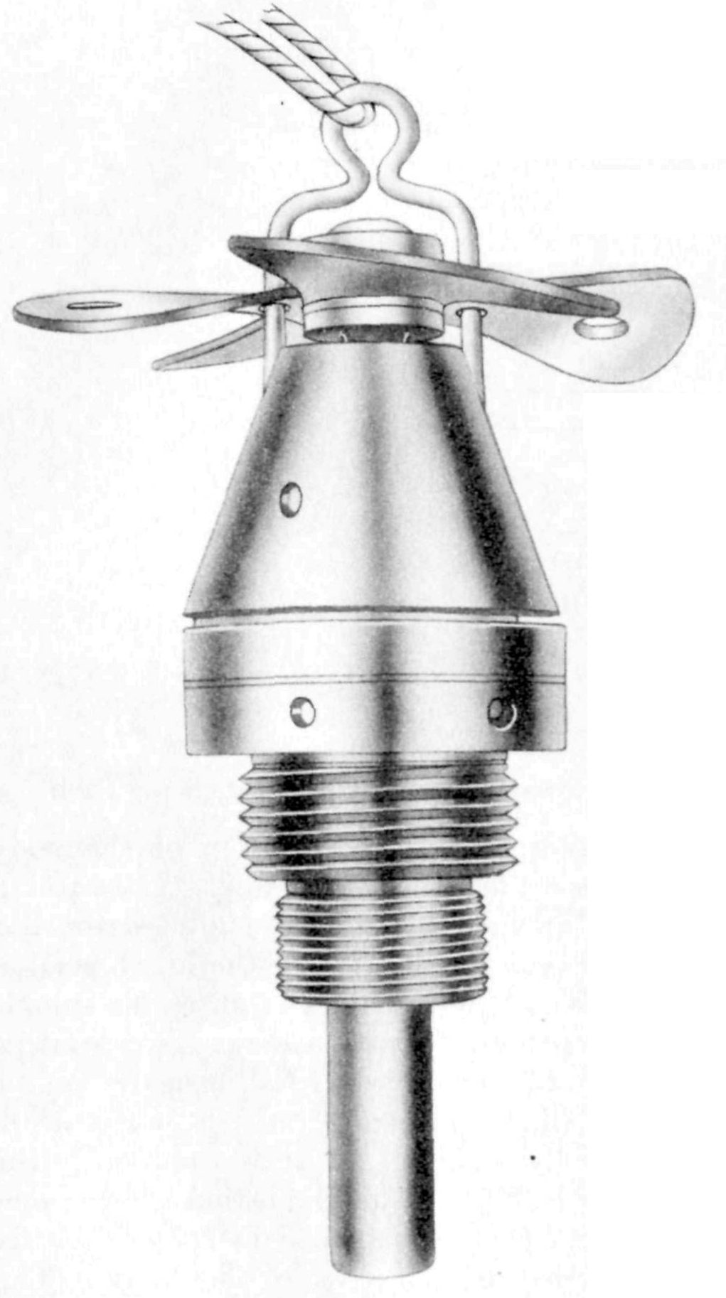
Upper fuze body houses striker assembly, the upper end of which is threaded for the arming vanes which are prevented from rotating during shipment by a U- shaped safety fork fitting into holes. A locating pin fits into the groove in the striker spindle preventing rotation during arming time. The lower fuze body contains primer flash cap, delay train, flash channel and black powder relay. The spring prevents the striker from moving down on the primer flash cap after fuze is armed.
Functioning
On release, arming wire is withdrawn allowing vanes to rotate and fall free in eleven turns. On impact, the firing pin moves in against the spring and pierces the cap. The flash passes through channel and ignites delay train, the gas from burning powder escaping through escape hole. The delay train burns around the periphery to flash channel, ignites powder relay, which in turn sets off the gaine and booster.
Hazardous Components
Flash cap, delay train, black powder relay, standard Army gaine, and picric booster.
Physical Data
Length, overall (no booster) - 5.4 in, 137.2 mm
Width, overall - 1.3 in, 33 mm
See Also
Source(s)
OP 1667, Japanese Explosive Ordnance, Volume 1 (1946)
USNBD - Japanese Bombs & Fuzes (1944)
TM-E9-1984, Enemy Bombs and Fuzes, Section VII, Japanese Fuzes (1942)
