Description
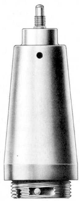
The fuze body is constructed in two parts - the lower body housing the firing components, and the upper body forming a cap extending well above the lower body and housing the arming components. In the upper body is a large inertia block having an arming spindle extending out of the fuze body. The vanes are screwed on this spindle and hold the block in position. A shear wire prevents rotation of the inertia block. On the lower surface of the block are four plungers located around a central extension which rests against a spring. This spring, when compressed by the downward movement of the inertia block, puts pressure on the striker located in the lower body. Bearing against a concave portion on the side of the striker is a steel detent held in place by a soluble plug. Also located in the lower body, and directly under the inertia block plungers is a copper tank containing acetone. A channel leads from the tank to the soluble plug.
Anti-withdrawal - A steel ball in the threads of the fuze locks the fuze when an attempt is made to withdraw it.
Functioning
On release from the plane, the arming wire is withdrawn and the vanes unscrew and fall free, leaving the inertia block to be held back by the shear wire which is sheared on impact. The inertia block, moving down after impact, is locked in the down position by the spring-loaded detent. At the moment that the inertia block moved down and the plungers pierced the acetone tank, the spring was compressed; the striker was then under pressure. The acetone from the tank contacts the soluble plug. When the plug dissolves, the striker moves forward under spring pressure and pierces the gaine. A steel ball locks the fuze in the pocket to prevent withdrawal.
Delays for three models of this fuze as stated in captured documents are below. Numbers in parenthesis indicate delays from testing.
Model 1 - 2-12 hours delay
Model 2 - 12-72 hours delay (17 1/4 actual)
Model 3 - 72-120 hours delay (24 1/2 actual)
Hazardous Components
Standard Navy gaine.
Physical Data
Length, overall - 6.1 in, 154.9 mm
Width, overall - 2.45 in, 62.2 mm
See Also
Bomb, 60 kg Land, Type 97 No. 6
Source(s)
OP 1667, Japanese Explosive Ordnance, Volume 1 (1946)
USNBD - Japanese Bombs & Fuzes (1944)
TM-E9-1984, Enemy Bombs and Fuzes, Section VII, Japanese Fuzes (1942)
